Polarization Optics Setup Diagram
A realistic infographic-style scientific diagram detailing an optical breadboard setup for dual-modulation phase and polarization control.
Budget models do not render typography reliably; this case needs a higher tier.
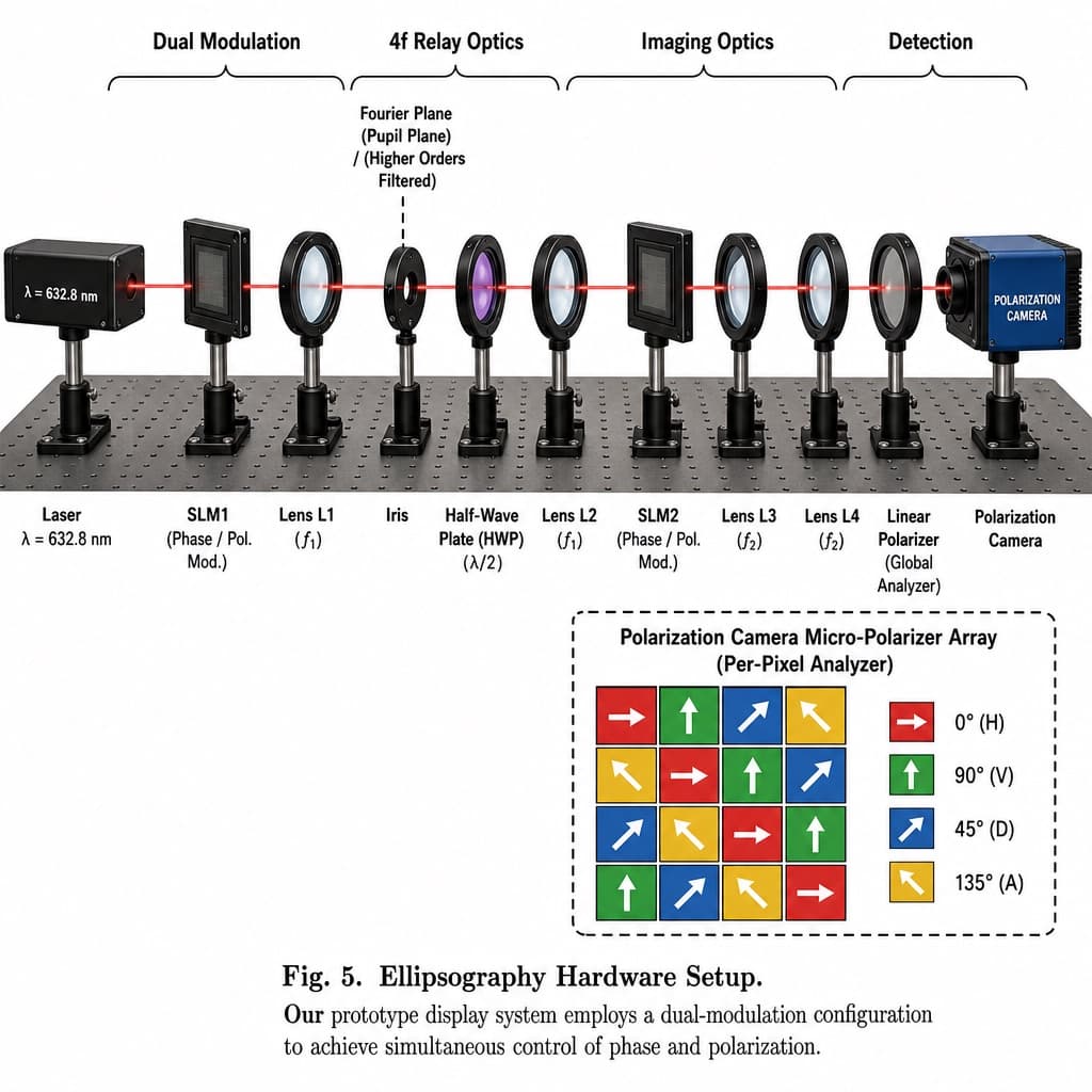
Image generated by us with gpt-image-2. Prompt by @HumanOS_v2
Prompt
Create a detailed scientific infographic-style diagram of an optical setup, rendered in a realistic technical illustration style. Show an optical breadboard table with a grid of mounting holes as the base, with a red laser beam passing horizontally through all components. Above the setup, include grouping brackets labeled '[COMPONENT_GROUP_LABEL]', '4f Relay Optics', 'Imaging Optics', and 'Detection'. Arrange the following components left to right along the beam path: a Laser (black rectangular box) labeled '[LASER_WAVELENGTH]'; SLM1, a black square device on a post labeled '(Phase / Pol. Mod.)'; Lens L1, a lens in a black ring mount labeled '(f1)'; an Iris with a dashed line above it, labeled 'Fourier Plane (Pupil Plane) / (Higher Orders Filtered)'; a Half-Wave Plate (HWP), a purple-tinted optic in a black ring mount labeled '(λ/2)'; Lens L2, a lens in a black ring mount labeled '(f1)'; SLM2, a black square device on a post labeled '(Phase / Pol. Mod.)'; Lens L3, a lens in a black ring mount labeled '(f2)'; Lens L4, a lens in a black ring mount labeled '(f2)'; a Linear Polarizer, a lens in a black ring mount labeled '(Global Analyzer)'; and a Polarization Camera, a blue and black box camera labeled 'POLARIZATION CAMERA'. In the bottom right corner, add an inset diagram with a dashed border titled '[INSET_TITLE] (Per-Pixel Analyzer)', showing a 4x4 grid of colored squares with white directional arrows, accompanied by a four-item legend: a red right-pointing arrow for 0° (H), a green up-pointing arrow for 90° (V), a blue diagonal arrow for 45° (D), and a yellow diagonal arrow for 135° (A). Below the main diagram, add a caption reading 'Fig. 5. [SETUP_TITLE]' followed by the descriptive text: '[FIGURE_CAPTION]'.
5 placeholders still empty. Copied as is, the generator will draw the brackets literally inside the image.
Editable variables
Change any value and the prompt rewrites above. Copy the finished result.
Label for the first grouping bracket describing the initial component category.
Text label showing the wavelength value of the laser source.
Title text for the bottom-right inset diagram describing the micro-polarizer array.
Title of the overall experimental setup shown in the figure caption.
Detailed descriptive caption explaining the function and purpose of the optical setup.
Generate the image here
With your own OpenAI key. Free for us, and what you spend is yours.
Kept in this browser only and sent straight to OpenAI's API: it never passes through a server of ours, because there is no server of ours in between. Check it yourself in the network tab.
Fill in the remaining variables before generating, or the model will draw the brackets.