Camera Imaging System Breakdown
A detailed technical infographic poster illustrating the exploded internal components and image-processing pipeline of a professional camera system.
Budget models do not render typography reliably; this case needs a higher tier.
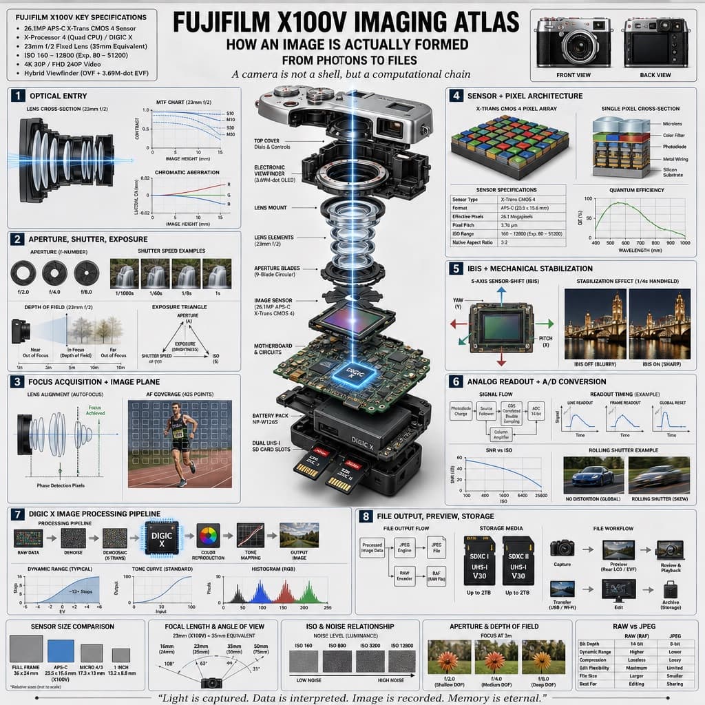
Image generated by us with gpt-image-2. Prompt by @hx831126
Prompt
Design a highly detailed technical infographic and exploded-view diagram poster explaining how a camera captures and processes an image, rendered in a clean, technical, photorealistic style with blueprint-style annotations, a light gray background, and precise typography.

Header: Display the main title '[CAMERA_MODEL] IMAGING ATLAS' prominently at the top. Below it, include three subtitles: 'HOW AN IMAGE IS ACTUALLY FORMED', 'FROM PHOTONS TO FILES', and 'A camera is not a shell, but a computational chain'. In the top-left corner, place a box titled '[CAMERA_MODEL] KEY SPECIFICATIONS' containing 6 bullet points of key specifications. In the top-right corner, place two images showing the front and back views of the camera body.

Centerpiece: In the middle of the poster, render a highly detailed 3D exploded view of the [CAMERA_MODEL] camera, showing its internal components separated vertically along a central axis. Visible components should include: the lens mount, lens elements with glowing blue light rays passing through them, the image sensor, the motherboard with a glowing [PROCESSOR_NAME] chip, the battery pack, dual memory card slots, and the electronic viewfinder (EVF).

Layout: Arrange eight numbered technical sections around the centerpiece, each with a title and supporting diagrams, graphs, or photos:
1. OPTICAL ENTRY — a lens cross-section with light rays and 2 line graphs.
2. APERTURE, SHUTTER, EXPOSURE — 3 aperture blade diagrams, 4 shutter speed example photos, a depth of field diagram, and an exposure triangle diagram.
3. FOCUS ACQUISITION + IMAGE PLANE — a lens alignment diagram and an autofocus coverage photo of a runner.
4. SENSOR + PIXEL ARCHITECTURE — a 3D pixel array diagram, a single pixel cross-section diagram, a sensor spec table, and a quantum efficiency graph.
5. IBIS + MECHANICAL STABILIZATION — a sensor-shift mechanism diagram showing yaw/pitch/roll axes, and 2 stabilization effect comparison photos.
6. ANALOG READOUT + A/D CONVERSION — a signal flowchart, 3 readout timing graphs, a signal-to-noise ratio graph, and a rolling shutter example photo of a car.
7. [PROCESSOR_NAME] IMAGE PROCESSING PIPELINE — a processing flowchart with the central chip, a dynamic range graph, a tone curve graph, and a histogram.
8. FILE OUTPUT, PREVIEW, STORAGE — a file output flowchart, 2 storage card icons, and a file workflow diagram.

At the bottom, include 5 comparison panels labeled: 'SENSOR SIZE COMPARISON', 'FOCAL LENGTH & ANGLE OF VIEW', 'ISO & NOISE RELATIONSHIP', 'APERTURE & DEPTH OF FIELD', and 'RAW vs JPEG'.

Footer: Display the quote '[FOOTER_QUOTE]' at the very bottom of the poster.

Overall style: clean, technical, highly detailed, with photorealistic rendering of components, blueprint-style annotations, a light gray background, and precise, legible typography throughout.
6 placeholders still empty. Copied as is, the generator will draw the brackets literally inside the image.
Editable variables
Change any value and the prompt rewrites above. Copy the finished result.
The name of the camera product model featured as the subject of the imaging system breakdown.
The name of the internal image-processing chip shown on the motherboard and referenced in the pipeline section.
A short bilingual closing quote placed at the bottom of the poster summarizing the imaging process.
Generate the image here
With your own OpenAI key. Free for us, and what you spend is yours.
Kept in this browser only and sent straight to OpenAI's API: it never passes through a server of ours, because there is no server of ours in between. Check it yourself in the network tab.
Fill in the remaining variables before generating, or the model will draw the brackets.